AGV Sensors: Vision Systems for Industrial Automation

AGV Sensors: Vision Systems for Industrial Automation

In-Depth Guide to Photoelectric Sensors

Photoelectric sensors are electronic devices that utilize optical principles for detection. They operate by emitting a light beam and sensing changes in that beam to identify the presence of specific objects or conditions. This non-contact detection method makes them crucial components in modern industrial applications.

Working Principle and Technical Features

The core component of a photoelectric sensor is its light-sensitive element. The sensor’s emitter projects a modulated light beam. When this beam encounters a target object, the light path undergoes changes. The receiver detects these alterations and converts the optical signals into electrical signals. After amplification and processing by the circuit, the output state is controlled.

These sensors offer several technical advantages. First, they enable non-contact detection without damaging target objects. Second, they provide relatively long detection ranges, significantly surpassing proximity sensors. Additionally, they offer extremely fast response times, typically reaching millisecond levels. Photoelectric sensors can also detect various materials, including glass and plastics.

Main Types and Application Scenarios

Through-beam sensors consist of separate emitter and receiver units. The emitter continuously projects a light beam, while the receiver detects it. When an object interrupts the beam, the sensor triggers an output signal. This type offers long detection distances and strong interference resistance, making it suitable for detecting large or opaque objects.

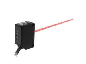
Diffuse-reflective sensors integrate both emitter and receiver into a single housing. They operate by detecting light reflected from the target object. With moderate detection ranges and easy installation, they’re widely used in packaging lines and material handling applications.

Retro-reflective sensors utilize specialized reflectors. The sensor triggers when an object interrupts the beam between the sensor and reflector. This configuration provides longer detection distances and remains unaffected by object color variations, commonly employed in access control systems and automated storage systems.

Key Performance Parameters Analysis

Detection range represents a crucial specification, indicating the maximum distance at which the sensor can reliably detect objects. Through-beam sensors can achieve ranges of tens of meters, while diffuse-reflective types typically operate within several meters.

Response time determines detection speed. High-quality sensors achieve response times as short as 1 millisecond, ensuring stable operation in high-speed production lines.

Environmental resistance is equally important. Protection ratings should reach at least IP67 to guarantee dust and water resistance. Operating temperature ranges typically span from -25℃ to +55℃. These characteristics ensure reliable performance in industrial environments.

Specific Applications in AGV Systems

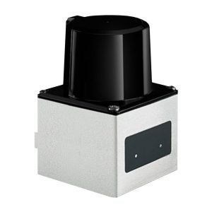
In Automated Guided Vehicle systems, photoelectric sensors perform multiple critical functions. They enable precise position detection, ensuring accurate docking at stations. Through path detection capabilities, they maintain AGVs along predetermined routes.

Safety collision avoidance represents another vital application. These sensors form multi-layer protection systems, capable of promptly detecting obstacles ahead to initiate emergency braking. This application effectively prevents potential collision incidents.

Material detection serves as another key function. Sensors verify cargo presence on shelves and enable precise positioning of goods, ensuring handling accuracy. These combined functions significantly enhance warehouse operational efficiency.

Selection and Installation Guidelines

Several factors require consideration when selecting sensors. Detection range must meet application requirements, while target material and color affect detection performance. Environmental conditions like dust and humidity also need careful evaluation.

During installation, proper beam alignment is essential. Maintain appropriate distance between sensors and target objects, and avoid direct strong light exposure to receivers to prevent false triggering. Regular cleaning of optical windows maintains detection reliability.

Development Trends and Future Prospects

Photoelectric sensor technology continues to advance. Miniaturized designs save installation space, while intelligent features keep enhancing, including self-diagnosis and network communication capabilities. Multi-functional integration represents an emerging trend, incorporating measurement and recognition capabilities.

Industry 4.0 drives new developments. IoT technology enables remote monitoring, while data analysis functions enhance system intelligence. These innovations will further expand photoelectric sensors’ application domains across various industries.

Servo Drive Systems: Enabling Precision, Stability, and Intelligence in AGVs

Servo Drive Systems: Enabling Precision, Stability, and Intelligence in AGVs

On the stage of smart manufacturing, the precise movement of Automated Guided Vehicles (AGVs) is truly remarkable. They can dock with millimeter-level accuracy and smoothly transport loads weighing several tons, all thanks to a key system—the servo drive system. If navigation sensors are considered the “eyes” of an AGV, then the servo system is its robust and sensitive “muscles and nerves.”

The Secret to Precision Control

The servo drive system achieves precise control through the perfect coordination of three core components: the servo motor provides power, the encoder offers real-time positional feedback, and the servo drive acts as the intelligent command center. This system employs a unique closed-loop control mechanism, continuously comparing commands with actual conditions and making real-time adjustments to ensure the AGV strictly follows its preset trajectory.

Particularly noteworthy is its exceptional load-adaptive capability. The system can withstand 200% to 300% overload torque for several seconds, ensuring stable performance under varying loads. Whether operating empty or fully loaded, it maintains smooth movement, effectively preventing cargo shaking.

Excellent Performance Across Diverse Scenarios

The superior performance of the servo system shines in multiple fields:

In automotive manufacturing and semiconductor workshops, thanks to high-resolution encoders ranging from 17-bit to 24-bit, AGVs can achieve docking accuracy of ±5 mm, perfectly supporting automated assembly processes.

In the aerospace sector, servo systems provide peak torque of up to several thousand Newton-meters, enabling heavy-load AGVs to smoothly transport components weighing tens of tons.

In e-commerce warehouse sorting areas, speed response frequencies exceeding 500 Hz ensure AGVs can start, stop quickly, and turn precisely, significantly improving operational efficiency.

Even in cleanrooms or explosive environments, specially designed brushless and spark-free systems ensure safe and reliable operation.

Analysis of Key Performance Parameters

Parameter CategorySpecific MetricMeaning and Typical ValuesImpact on AGV Performance
Control AccuracyPositioning AccuracyDetermined by encoder resolution, typically 17-bit to 24-bit (equivalent to 131,072 to 16,777,216 pulses per revolution).Higher resolution enables finer position control, forming the basis for millimeter-level docking accuracy.
ResponsivenessSpeed Response FrequencyTypically >500 Hz.Higher frequency enables faster response to commands, ensuring smoother speed control and more seamless acceleration/deceleration.
Power PerformanceRated/Peak Torquee.g., 10 Nm / 30 Nm. Rated torque determines continuous load capacity, while peak torque indicates short-term overload/startup capability.Directly determines the AGV’s load capacity and acceleration performance.
Overload CapacityTypically capable of withstanding 200%-300% of rated torque for several seconds.Ensures the AGV can overcome inertia during startup, slope climbing, or when encountering resistance, preventing motor stall. 
Core CharacteristicClosed-Loop ControlThe system continuously monitors output and makes feedback adjustments, forming a closed loop.A fundamental characteristic that ensures control precision and resistance to disturbances. Open-loop systems cannot achieve precise control.

Technological Evolution and Future Prospects

Servo technology is evolving toward smarter and more integrated solutions. Integrated designs perfectly combine drives and motors, saving space while enhancing reliability. The application of EtherCAT bus control technology enables precise synchronization among multiple axes. Additionally, the integration of functions like Safe Torque Off (STO) provides higher levels of safety assurance.

Conclusion

As the core actuating component of AGVs, the servo drive system ensures precise and stable operation in complex industrial environments through sophisticated control algorithms and outstanding performance parameters. With ongoing technological innovations, this system will continue to elevate AGV performance to new heights, injecting stronger momentum into smart manufacturing.

The Laser Navigator: Enabling Precision and Flexibility for AGVs

The Laser Navigator: Enabling Precision and Flexibility for AGVs

The laser navigation sensor is the core component that gives an AGV its environmental perception and autonomous positioning capabilities. Its performance directly determines the AGV’s level of intelligence and operational accuracy.

I. Function: The Foundation of Environmental Perception and Autonomous Positioning

The laser sensor serves two core functions in an AGV system:

  1. Natural Feature Navigation

    • Principle: It builds a map by scanning and recording fixed features in the environment (e.g., walls, columns, fixed shelving). During operation, the AGV locates itself precisely by matching real-time scan data with this pre-stored map.

    • Advantage: It eliminates the need for any floor-mounted guides (like magnetic tape or QR codes). Path changes can be made via software, significantly enhancing system flexibility and scalability.

  2. Safety Obstacle Avoidance

    • Principle: Simultaneously with navigation, the laser sensor continuously scans a扇形 area in front of the AGV, creating one or more “virtual safety curtains.”

    • Data Examples:

      • Detection Range: Typically from 0.1 meters to 30 meters (depending on the model).

      • Scanning Frequency: Typically 10 Hz to 50 Hz (i.e., 10-50 scans per second), ensuring timely detection of dynamic obstacles.

      • Safety Zone Setup: Configurable warning zones (e.g., AGV slows down if an obstacle is detected 5 meters ahead) and stop zones (e.g., AGV brakes immediately if an obstacle is detected 2 meters ahead).

II. Accuracy & Density: Key Metrics Determining Navigation Precision

Accuracy and angular resolution are the core parameters for measuring laser sensor performance.

  1. Absolute Positioning Accuracy

    • Definition: The error between the AGV’s self-calculated position (via laser定位) and its actual physical position.

    • Typical Data: The positioning accuracy of commercial AGV-grade laser navigation sensors is typically ±10 mm or better. High-end models can achieve ±5 mm in environments with clear features and good calibration.

  2. Angular Resolution & Ranging Accuracy

    • Angular Resolution: The angle between two adjacent laser beams, determining the sensor’s “fineness.”

      • Typical Data: Common AGV LiDAR angular resolution ranges from 0.25° to 0.5°. This means at 10 meters, it can distinguish between two objects about 4.4 cm apart (10m × tan(0.25°)).

    • Ranging Accuracy: The accuracy of the LiDAR’s distance measurement.

      • Typical Data: Typically ±10 mm to ±30 mm (over ranges of tens of meters).

  3. Scanning Range & Point Cloud Density

    • Scanning Range: The planar angle covered by the LiDAR, usually 270° or 360°.

    • Point Cloud Density: A higher angular resolution and scanning frequency result in a denser environmental point cloud, leading to more reliable positioning and obstacle avoidance.

III. Application Scenarios and Performance Data

The characteristics of laser navigation sensors make them excel in specific scenarios:

  1. Large-Scale Flexible Manufacturing Workshops

    • Scenario: Automotive assembly lines, electronics production lines where paths need frequent changes.

    • Performance Data: With laser navigation, AGV path change implementation time can be reduced from several days (re-laying tape) to a few hours (software modification), significantly boosting production efficiency.

  2. Warehousing and Logistics Centers

    • Scenario: High-bay warehouses with narrow aisles shared with personnel.

    • Performance Data: With ±10 mm positioning accuracy, AGVs can safely navigate aisles only 10-15 cm wider than the vehicle itself, achieving space utilization rates over 98%.

  3. Dynamic Mixed Environments

    • Scenario: Areas shared with personnel and other equipment like forklifts.

    • Performance Data: By setting up multiple safety zones, AGVs can implement graded warnings and braking, minimizing the risk of collision and ensuring safe 7×24 uninterrupted operation.


Summary: The laser navigation sensor, with its high accuracy (millimeter-level), high flexibility (no floor modifications), and high reliability (real-time obstacle avoidance), is an indispensable “eye” for modern intelligent AGVs. Its performance data directly determines whether the AGV system can perform tasks stably and efficiently in complex, dynamic industrial environments.

AGV Encoders: The Precision Controllers of Intelligent Logistics

AGV Encoders: The Precision Controllers of Intelligent Logistics

In modern automated logistics and smart manufacturing systems, Automated Guided Vehicles (AGVs) are playing an increasingly vital role. Behind these “movers,” enabling their precise movement, lies a seemingly inconspicuous yet crucial core component – the encoder. Acting as the “sensory nerves” and “muscle memory” of AGVs, encoders ensure precise operation in complex environments through accurate measurement and real-time feedback.

I. Core Functions of Encoders

An encoder is essentially a sensor that converts mechanical motion into electrical signals. Within an AGV system, it is responsible for monitoring and providing real-time feedback on key data such as the drive wheel speed, steering wheel angle, and lift mechanism position. This data forms the basis of closed-loop control, enabling the AGV to follow preset paths accurately and complete various complex tasks.

From a technical principle perspective, encoders convert mechanical displacement into digital signals via photoelectric or magnetic electric effects. Taking a common incremental encoder as an example, its internal grating disk generates pulse signals when rotating; each pulse corresponds to a specific angular displacement. By counting these pulses, the control system can precisely calculate the AGV’s travel distance and speed.

II. Key Applications of Encoders in AGVs

  1. Travel Speed Control
    Incremental encoders are typically installed on the drive wheel motors of AGVs. For instance, a specific brand’s ENI58IL series encoder offers a resolution of up to 5000 pulses per revolution. Coupled with sophisticated motion control algorithms, this enables positioning accuracy of ±1mm. This high-precision control ensures the AGV remains stable even at high speeds and stops accurately at designated locations.

  2. Steering Angle Control
    For AGVs requiring flexible steering, multi-turn absolute encoders are indispensable. These encoders use special mechanical structures and signal processing technology to record the absolute angle of the steering wheel from its zero position. Even in the event of a power failure, their “power-off memory” function ensures no recalibration is needed upon restart. A typical steering encoder model offers a single-turn resolution of 16 bits (65,536 positions), fully meeting the requirements for precise AGV steering.

  3. Lift Position Control
    In AGV forklift applications, wire-draw encoders precisely calculate the fork height by measuring the extension and retraction of a wire. A high-end model of wire-draw encoder can achieve repeatability of ±0.01%. This means within a 4-meter lifting range, the positioning error does not exceed 0.4 millimeters. This level of accuracy ensures the AGV forklift can place goods into designated storage locations precisely.

III. Key Technical Parameters and Selection Criteria

When selecting an encoder for an AGV, the following technical parameters are crucial:

  1. Resolution and Accuracy
    Resolution determines the fineness of motion control, while accuracy directly affects the control’s correctness. For AGV applications, encoders with a resolution no less than 1000 pulses per revolution and an accuracy grade of at least ±5 arcseconds are typically required.

  2. Protection Rating
    Since AGVs often operate in dusty, damp industrial environments, encoders should have a protection rating of at least IP65, with IP67 needed for harsher conditions, ensuring long-term stable operation.

  3. Interface Type
    Modern AGV systems usually require encoders to support fieldbus interfaces like CANopen or EtherCAT. These digital interfaces offer fast transmission speeds and strong noise immunity, meeting the demands of real-time control.

  4. Mechanical Characteristics
    The shaft load capacity, speed limits, and vibration resistance of an encoder directly impact its service life. High-quality encoders can withstand at least 20N axial load and 30N radial load, with vibration resistance exceeding 30g.

IV. Installation and Maintenance Essentials

Correct installation is a prerequisite for reliable encoder operation. Speed encoders need to be connected directly to the motor shaft via precision shaft sleeves, ensuring runout error is within 0.1mm. Installation of steering encoders must avoid measurement errors caused by gear backlash. Wire-draw encoders require the wire to be strictly parallel to the direction of movement to prevent uneven wear.

During routine maintenance, regularly check the encoder’s connection status, clean optical components (for photoelectric encoders), and inspect the integrity of the cable shielding. A comprehensive inspection and calibration every 2000 operating hours is recommended.

V. Future Development Trends

As AGVs evolve towards higher speeds and greater precision, encoder technology is also innovating. New-generation magnetic encoders, known for their superior environmental resilience and longer service life, are gradually replacing traditional photoelectric encoders. Simultaneously, smart encoders with integrated diagnostic functions are emerging, capable of monitoring their own status and providing early warnings for potential failures.

Furthermore, single-cable solutions (like EnDat 3) are becoming an industry trend. This technology integrates power and signal transmission into a single cable, simplifying wiring and enhancing system reliability.

Conclusion

In the rapidly developing fields of smart manufacturing and intelligent logistics, the importance of encoders as core components of AGVs is self-evident. Selecting the right encoder and ensuring its correct installation and maintenance are key to guaranteeing the stable and efficient operation of AGV systems. With continuous technological progress, encoders will continue to propel AGVs towards greater intelligence and precision, injecting fresh vitality into industrial automation.

Reflector Plate Navigation: The Selection Guide for AGV Laser Positioning’s “High-Precision Landmarks”

Reflector Plate Navigation: The Selection Guide for AGV Laser Positioning’s “High-Precision Landmarks”

In AGV laser navigation systems, reflector plates serve as celestial stars in the night sky, providing absolute coordinate references for mobile robots. As core ground infrastructure enabling centimeter-level accuracy, reflector plates have become the preferred navigation solution for precision-driven scenarios like smart factories and medical logistics, leveraging their stable reflective properties.


Reflector Plates: The Precision Foundation of Laser Navigation
Reflector plates are constructed from micro-prism arrays or glass bead coatings, reflecting incident laser light along its original path (80%–98% reflection efficiency). When an AGV’s laser scanner (LiDAR) detects three or more reflector plates, it achieves ±5 mm absolute positioning accuracy through triangulation algorithms.

Core Performance Indicators:

Parameter

Standard Range

Impact on Accuracy

Reflectivity

80%–98%

≥90% ensures stable recognition within 30 m

Angular Tolerance

±25°–±45°

Higher tolerance increases installation flexibility

Environmental Rating

IP65–IP69K

Determines resistance to dust, oil, and water corrosion

Thermal Expansion

≤5×10⁻⁶/℃

Prevents positioning drift due to thermal deformation


Scientific Selection: Five Scenario-Matching Dimensions

1.Scenario-Based Reflectivity Grading

Standard Workshops (illumination <1000 lux):
Glass bead coating plates (85% reflectivity, 30% cost reduction).

High-Interference Zones (glass walls/welding shops):
Micro-prism plates (>95% reflectivity, 1:10 sunlight suppression ratio).


2.Installation Method Defines Structural Strength

Scenario Impact

Recommended Type

Durability

Light AGVs (≤1 ton)

Adhesive aluminum-plastic plates (1.2mm)

Withstands 100,000 air impact cycles

Heavy Forklift AGVs

Bolt-fixed stainless steel plates (3mm)

Resists 50-ton crushing without deformation


3.Material Upgrades for Extreme Environments

-30°C Cold Storage: Polycarbonate base (resists low-temperature brittleness; >90% elastic modulus retention).

Electroplating Workshops: 316L stainless steel casing + fluorocarbon coating (acid/alkali resistance: pH 1–13).

Outdoor Sites: Anodized aluminum plates (UV-resistant lifespan >10 years).


4.Layout Planning and Precision Optimization

±5 mm precision: 8–12 plates per 100㎡, spaced 5–8 m in non-symmetrical distribution.

±10 mm precision: 5–8 plates per 100㎡, spaced 8–12 m.


Critical: Uniform height (recommended: 1.2 m); adjacent plate angles >30° to prevent misidentification.


5.Hidden Maintenance Cost Factors

Cleaning cycle: Quarterly wiping in dusty environments (replace if reflectivity loss >15%).

Displacement monitoring: Mounting bases require scaled positioning slots (>0.5 mm displacement causes positioning failure).


Critical Pitfalls: Mistakes in 90% of Projects

Unverified Reflectivity Claims: Failure to test with spectrophotometers (40% positioning failure rate if reflectivity <80%).

Mirror Interference: Missing light shields near glass walls/metal tanks (secondary reflections cause coordinate drift).

Multipath Interference: Over-dense layouts in pipe-intensive areas (laser misidentification of adjacent reflectors).

Ignoring Thermal Deformation: Using ABS plastic plates in >50°C delta-T environments (3 mm/m expansion error).

Technology Advance: Smart encoded reflector plates (embedded ID chips) resolve multi-AGV interference, boosting positioning stability by 200%.


Why Professional Selection Determines Success?
Generic solutions pose significant risks if your project involves:


Glass-walled factories with intense light interference

High-vibration stamping workshops

Ultra-high precision (±5 mm) requirements

Flexible production lines with monthly route changes


We Deliver Game-Changing Solutions:

Free Site Survey: Laser-scanned ambient interference + vibration spectrum analysis.

Reflectivity Validation: Third-party certified reports (ISO 17482 compliant).

Dynamic Simulation Design: Layout density optimized via AGV flow prediction.

Rapid Replacement System: Snap-on bases enable 10-minute route reconfiguration.


Reflector Plate Navigation: The Selection Guide for AGV Laser Positioning’s “High-Precision Landmarks”

Reflector Plate Navigation: The Selection Guide for AGV Laser Positioning’s “High-Precision Landmarks”

In AGV laser navigation systems, reflector plates act like stars in the night sky, providing absolute coordinate references for mobile robots. As core ground infrastructure enabling centimeter-level accuracy, reflector plates have become the preferred navigation solution for precision-driven scenarios like smart factories and medical logistics, thanks to their stable reflective properties.


Reflector Plates: The Precision Foundation for Laser Navigation
Reflector plates consist of micro-prism arrays or glass bead coatings, reflecting incident laser light along its original path (reflection efficiency: 80%–98%). When an AGV’s laser scanner (LiDAR) detects three or more reflector plates, it achieves absolute positioning accuracy of ±5 mm through triangulation algorithms.

Core Performance Indicators:

Parameter

Typical Range

Impact on Accuracy

Reflectivity

80%–98%

>=90% ensures stable identification within 30 m

Angular Tolerance

±25°–±45°

Higher tolerance allows greater installation flexibility

Environmental Rating

IP65–IP69K

Determines resistance to dust, oil, and water corrosion

Thermal Expansion

<=5×10⁻⁶/℃

Prevents positioning drift due to temperature deformation


Scientific Selection: Five Dimensions for Scenario Matching

1.Reflective Performance by Scenario

Standard Workshops (illumination <1000 lux):
Use glass bead coating plates (85% reflectivity, 30% cost reduction).

High-Interference Zones (e.g., glass walls/welding shops):
Mandatory micro-prism plates (>95% reflectivity, 1:10 sunlight suppression ratio).


2.Installation Method Determines Structural Strength


Scenario Impact

Recommended Type

Durability

Light AGVs (<=1 ton)

Adhesive aluminum-plastic plates (1.2mm thick)

Withstands 100,000 air impact cycles

Heavy Forklift AGVs

Bolt-fixed stainless steel plates (3mm thick)

Resists 50-ton crushing without deformation


3.Material Upgrades for Extreme Environments

-30°C Cold Storage: Polycarbonate base (resists low-temperature brittleness; >90% elastic modulus retention).

Electroplating Workshops: 316L stainless steel casing + fluorocarbon coating (acid/alkali resistance: pH 1–13).

Outdoor Sites: Anodized aluminum plates (UV-resistant lifespan >10 years).


4.Layout Planning and Precision Correlation

±5 mm precision: 8–12 plates per 100㎡, spaced 5–8 m in asymmetric distribution.

±10 mm precision: 5–8 plates per 100㎡, spaced 8–12 m.
Critical: Plates must be uniform height (recommended: 1.2 m); adjacent plate angles >30° to avoid misidentification.


5.Hidden Maintenance Cost Traps

Cleaning cycle: Wipe quarterly in dusty environments (replace if reflectivity loss >15%).

Displacement monitoring: Mounting bases require scaled positioning slots (displacement >0.5 mm causes positioning failure).


Critical Pitfalls: Mistakes in 90% of Projects

Inflated Reflectivity Claims: Failure to verify with spectrophotometers (positioning failure rate reaches 40% if actual reflectivity <80%).

Mirror Interference: Omission of light shields near glass walls or metal tanks (secondary reflections cause coordinate drift).

Multipath Interference: Over-dense layouts in pipe-intensive areas (misidentification of adjacent reflectors).

Thermal Deformation Neglect: Using ABS plastic plates in >50°C delta-T environments (expansion error reaches 3 mm/m).

Tech Advancement: Smart encoded reflector plates (with embedded ID chips) resolve multi-AGV interference, boosting positioning stability by 200%.


Why Professional Selection Determines Success?
Generic solutions pose significant risks if your project faces:

Glass-walled factories with strong light interference

High-vibration stamping workshops

Ultra-high precision requirements (±5 mm)

Flexible production lines with monthly route changes


We Deliver Game-Changing Solutions:

Free Site Survey: Laser-scanned ambient interference + vibration spectrum analysis.

Reflectivity Testing: Third-party certified reports (ISO 17482 compliant).

Dynamic Simulation Design: Layout density optimized via AGV flow prediction.

Rapid Replacement System: Snap-on bases enable 10-minute route reconfiguration.


RFID Navigation Tags: The Selection Guide for AGV Smart Systems’ “Invisible Coordinates”

RFID Navigation Tags: The Selection Guide for AGV Smart Systems’ “Invisible Coordinates”

In modern smart logistics and flexible manufacturing systems, AGV (Automated Guided Vehicle) positioning functions like the human sensory nervous system, with RFID tags serving as the critical “coordinate points” embedded on the ground. As a core facility for discrete navigation, RFID tags are becoming a popular choice for AGV intelligence upgrades due to their flexible deployment and dual advantages in information exchange.


RFID Tags: The Discrete Navigation Foundation for AGVs
RFID (Radio Frequency Identification) tags consist of a chip and antenna, enabling centimeter-level point positioning and command transmission through contactless communication with AGV-mounted readers via electromagnetic fields. Their core value lies in:


Passive Operation: No power supply required; activated by energy from the reader (effective lifespan >10 years).


Data Carrier: Stores critical information such as station codes and path commands (capacity: 1kb–8kb).


Environmental Penetration: Capable of penetrating non-metallic materials (e.g., wood, plastic), adapting to complex conditions.


Key Performance Elements:

Parameter Dimension

Typical Indicators

Navigation Impact

Operating Frequency

LF 125kHz / HF 13.56MHz / UHF 860-960MHz

LF: Strong metal resistance; UHF: Long read range

Protection Rating

IP67 / IP68 / IP69K

Determines resistance to oil, water, and chemical corrosion

Installation Method

Surface Adhesive / Embedded / Bolted

Affects crush resistance (up to 20 tons)


Scientific Selection: Four-Dimensional Matching Principles


1.Frequency & Material Determined by Scenario

Metal Environments (e.g., near machinery, racking areas):
Prefer metal-resistant tags (with ferrite magnetic layer), LF 125kHz, stable read range of 10–30 cm.

High-Traffic Pathways (e.g., sorting lines, intersections):
Use UHF tags with 2–8 m read range, supporting dynamic recognition of high-speed AGVs.

Wet/Corrosive Areas:
Opt for ceramic-encapsulated tags (IP69K) with epoxy resin sealing, resistant to acid/alkaline cleaning.


2.Installation Method Matched to Precision Needs


Precision Requirement

Recommended Solution

Implementation Principle

Centimeter-Level

Embedded tags (grooved into floor)

Flush with ground surface to avoid displacement from impact

Decimeter-Level

Surface-adhesive tags

Rapid deployment, 40% cost reduction

*Note: For embedding depth >3 cm, select high-power tags (e.g., +5dBm gain antenna).*


3.Chip Grade Determined by Data Interaction Depth

Basic Navigation: Read-only tags (store path ID; cost <$0.50 per unit).

Smart Interaction: Read-write tags (update task commands in real-time; support NTAG213 protocol).


4.Survival Design for Extreme Environments

-40°C Cold Chain Warehouses: Silicone material tags (resistant to low-temperature brittleness).

High-Temp Foundries: Ceramic tags (withstands >200°C).

High-Pressure Washdown Zones: Fully sealed stainless steel housing (resists 120 Bar water impact).


Pitfall Avoidance: Critical Errors in RFID Applications

Metal Interference Blind Spots: Failure to use metal-resistant tags causes read failures (>90% failure rate in metal environments).

Tag Collision: Omission of anti-collision algorithms in dense deployments (standard protocol: ISO 18000-6C).

Height Mismatch: Reader-tag distance exceeding specifications (UHF tags require control within 1.5× wavelength).

Data Security Gaps: Failure to enable encryption protocols (recommended: AES-128 or DESFire EV2).


Magnetic Strip Navigation: The Selection Guide for AGV Smart Transport’s “Invisible Track”

Magnetic Strip Navigation: The Selection Guide for AGV Smart Transport’s “Invisible Track”

In modern intelligent warehousing and manufacturing systems, AGVs (Automated Guided Vehicles) act like flowing “blood vessels,” while magnetic strips serve as the “track nerves” determining their operational precision. As a core component of ground navigation, magnetic strips, known for their stability and cost-effectiveness, are indispensable accessories in numerous AGV systems.


Magnetic Strips: The Reliable Ground Navigator for AGVs
Magnetic strips are soft magnetic composite materials made from bonded ferrite powder and synthetic rubber through a calendering process, offering both flexibility and magnetic strength. Their backs are typically coated with double-sided adhesive tape, allowing them to be directly laid on the ground to form navigation paths. AGVs use onboard magnetic navigation sensors to identify the magnetic field signals, achieving high-precision positioning within ±5mm.


Core performance parameters directly impact navigation reliability:

Magnetic Properties: Remanence (2000-2810 Gauss) and Coercivity (145-2400 kA/m) determine magnetic field stability and anti-interference capability.

Physical Specifications: Common widths range from 20-50mm (standard is 30mm), with thicknesses of 1.2-3mm (lightweight) or 10mm (heavy-duty embedded).

Environmental Suitability: Operating temperature range covers -20℃ to 60℃, with a Curie temperature as high as 150℃, ensuring no failure in high-temperature environments.


Scientific Selection: Four Key Dimensions to Match Your Scenario

1.Load & Environmental Intensity Dictate Strip Type:

Lightweight Adhesive Strips: Suitable for indoor flat floors, handling standard AGVs (≤1 ton). Directly adhere to epoxy or concrete floors, enabling quick deployment and route adjustments.

Heavy-duty Embedded Strips (e.g., 6×10mm): Designed for high-traffic scenarios like docks and freight hubs. Require grooving into the floor and sealing with silicone. Withstand crushing strength >10 MPa and can guide heavy-duty AGVs (up to 50 tons).


2.Environmental Tolerance Dictates Coating & Material Upgrades:

Wet/Oily Areas: Choose rubber-based strips covered with PVC tape or aluminum foil to prevent magnetic flux attenuation caused by iron powder adhesion.

Outdoor Scenarios: Use high-coercivity magnetic material (Hc >20 kOe) combined with waterproof sealing processes to resist rain erosion, achieving 99.9% reliability.


3.Magnetic Parameters Must Precisely Match AGV Sensors:


The remanence strength of the magnetic strip must correspond to the sensitivity of the AGV’s magnetic sensor:

2000 Gauss level: Suitable for standard sensors with 1-2m detection height.

2800 Gauss level and above: Used for deeply embedded (>50mm) scenarios or where penetration through floor coverings is needed.


Magnetic pole orientation (N-pole upwards) must be strictly uniform, and connection gaps must be controlled to less than 2mm to avoid signal interruption.


4.Balancing Lifespan & Maintenance Costs:


The natural demagnetization cycle of magnetic strips is approximately 12-18 months. Selection should consider:

Temperature Coefficient: Remanence temperature coefficient is -0.02%/℃ (lower attenuation in low temperatures).

Protective Design: Surface coverage with wear-resistant tape can extend lifespan by over 30%.

Segmented Replacement Feasibility: Prioritize standard roll-mounted strips (50m/roll) for flexible cutting.


Pitfall Avoidance: Common Mistakes in Magnetic Strip Application

Avoid Installation On/In: Ferrous foundations (causes magnetic attenuation), near strong magnetic equipment (magnetic interference), or areas exposed to chemicals (solvent corrosion of adhesive layer).

Common Maintenance Oversights: Neglecting iron powder cleaning (requires monthly inspections), failing to monitor connection gaps (displacement causing gaps >2mm), lacking reinforcement measures at turns (prone to crushing damage).

Technology Upgrade Potential: Hybrid navigation combining Magnetic Strips + Laser SLAM can improve positioning accuracy to within ±1mm.


Expert Tip: When facing complex conditions (e.g., high humidity, ultra-low temperatures, or frequent route changes), customized magnetic strip combination solutions can improve cost-effectiveness by 40% compared to generic models.


From workshops to ports, and from 1-ton light carts to 50-ton heavy-duty platforms, precise selection is the core prerequisite for AGV magnetic strips to perform effectively. If your project involves special floors, extreme environments, or high-precision navigation requirements, our technical team can provide comprehensive selection support, including magnetic circuit simulation analysis, environmental adaptation solutions, and lifecycle planning.


Contact us now to obtain a customized magnetic strip navigation solution – ensuring every AGV travels on the optimal path!


AGV Chassis and Structural Component Selection Guide: Performance Trade-offs Between Aluminum Profiles and Carbon Steel Sheet Metal

AGV Chassis and Structural Component Selection Guide: Performance Trade-offs Between Aluminum Profiles and Carbon Steel Sheet Metal

In AGV engineering architecture, the chassis and structural components function as the “skeletal system,” bearing the integrated loads of core modules like drive systems, navigation, and lifting mechanisms. Material selection and design directly determine an AGV’s load capacity, motion stability, and lifecycle costs. The performance trade-offs between lightweight aluminum profiles and high-strength carbon steel sheet metal must be precisely balanced against operational needs. This guide reveals core selection logic to help build a more reliable AGV foundation.


Chassis System: The “Mechanical Backbone” of AGVs

The chassis serves not only as a mechanical base but also as a physical medium for vibration transmission, impact absorption, and electromagnetic shielding. Its failure can trigger systemic risks. An optimal chassis must meet three key metrics:

1.Stiffness-to-Weight Ratio: ≥10 tons/m³ load capacity per unit mass (carbon steel: 15; aluminum alloy: 8).

2.Deformation Control: Maximum deflection ≤1/1000 span under full load (e.g., <1mm over 1m).

3.Modular Compatibility: Pre-configured interfaces support 20+ functional modules (e.g., lifters, robotic arms).


Industry Lesson: Resonance-induced fatigue fractures in a carbon steel chassis halted 10 logistics AGVs, causing over ¥2M in losses.


Aluminum Profile Chassis: Synonymous with Lightweight Agility

Innovative Design & Performance Limits

Precision lightweight structures via extrusion + CNC machining:


Core Specifications:

Material: 6061-T6 aluminum (310MPa tensile strength; 2.7g/cm³ density).

Cavity Structure: Multi-rib hollow design (3–8mm wall thickness; +40% stiffness).

Surface: 15μm anodized coating (C5 corrosion resistance).


Key Advantages:

30% Weight Reduction: 300kg lighter than carbon steel at equal loads, reducing motor power.

Zero Welding Stress: T-slot + high-strength bolting (≥35N·m preload).

Cleanroom Compatibility: Non-magnetic, spark-free (pharmaceuticals/electronics).


Typical Applications:

Lightweight high-speed AGVs (≤1-ton load; ≥2m/s).

Cleanrooms, EMI-sensitive zones (e.g., semiconductor wafer handling).

Flexible production lines requiring frequent acceleration/deceleration.


Carbon Steel Sheet Metal Chassis: Fortress of Heavy-Duty Impact Resistance

Technological Breakthroughs & Value

High-toughness structures via laser cutting + robotic welding:


Core Processes:

Material: Q345B low-alloy steel (345MPa yield strength; 4–12mm thickness).

Structural Optimization: U-section beams + honeycomb cross-members (+60% torsional rigidity).

Weld Integrity: Ultrasonic testing + vibration stress relief (99.9% pass rate).


Performance Capabilities:

Extreme Loads: 5-ton capacity (fork-style AGVs).

Impact Resistance: Withstands 50g shocks (mining/port scenarios).

Cost Efficiency: Material costs 1/3 of aluminum.


Heavy-Duty Case:
A 10-ton automotive assembly AGV uses dual-layer carbon steel frames with localized quenching. Frame deflection remains <0.5mm when starting/stopping on 2° slopes under full load.


Selection Decision Matrix: 5 Dimensions for Precision Matching

Dimension

Aluminum Preferred

Carbon Steel Preferred

Load Intensity

≤1.5 tons

≥2 tons

Dynamic Response

High speed/acceleration (>1m/s²)

Steady transport (≤1.5m/s)

Environmental Corrosion

Acids/moisture

Dry/short-term outdoor

EMC Requirements

MRI rooms/precision labs

Standard industrial zones

Lifecycle Cost Focus

Energy savings

Lowest upfront cost

Key Validation Metrics:

Fatigue Life: Carbon steel—1M cycles (±3g vibration); aluminum—2M cycles.

Grounding Resistance: <0.1Ω classis-to-ground resistance (ESD-sensitive areas).

Interface Precision: Mounting surface flatness ≤0.1mm/m.


Engineering Empowerment: Forging an “Indestructible Body” for Your AGV

Chassis design integrates materials science, structural mechanics, and manufacturing. As an AGV structural partner, we deliver:


Scenario-Driven Customization

Hybrid Structures: Carbon steel main beams + aluminum sub-frames (strength/weight balance).

Extreme Environments:

Food-grade 304 stainless steel (acid resistance).

Explosion-proof designs (Ex d IIC T6 certified).


CAE Simulation:

Static load analysis (ANSYS Workbench).

Modal analysis to avoid resonance (>30Hz).


End-to-End Technical Support

Precision Assurance:

Laser tracker inspection (<±0.2mm dimensional error).

Welding deformation compensation algorithms.


Rapid Delivery:

Standard chassis: 3 days; custom solutions: 15 days.


Smart Monitoring:

Embedded strain sensors for real-time stress tracking.


Act Now for Three Exclusive Services:

1.Free Structural Simulation: Submit load/operational data for stress maps and optimization advice within 48 hours.

2.Prototype Load Testing: Validate chassis performance in real scenarios (with test report).

3.Lifetime Warranty: Free replacement for cracks/deformation (Year 1).


Durability Enables Reliability— Leverage our materials engineering expertise to armor your AGVs!


AGV-Specific Gripper Selection Guide: Precision Matching of Fork Arms and Robotic Grippers

AGV-Specific Gripper Selection Guide: Precision Matching of Fork Arms and Robotic Grippers

In AGV intelligent handling systems, specialized grippers function as “dexterous hands,” determining whether AGVs can efficiently and damage-free handle diverse materials. From standard pallets to irregular workpieces, from fragile glass to high-temperature metals, selecting fork arms or robotic grippers requires deep integration of material properties, operational scenarios, and safety standards. This guide systematically analyzes core gripper designs and selection strategies to unlock AGVs’ ultimate gripping potential.


Gripper Systems: The “Value Amplifier” of AGV Capabilities

Specialized grippers elevate AGVs from “transport tools” to “execution terminals,” demanding three key performance metrics:

1.Precision Adaptation: Tolerate material dimensional variations ≤±2mm (e.g., automotive battery mounting holes).

2.Damage-Free Handling: Adjustable contact pressure (0.5–5N/cm²) to protect delicate surfaces.

3.Rapid Changeover: Modular design enables tool switching (e.g., fork-to-suction) in ≤5 minutes.


Industry Lesson: Excessive force from a robotic gripper deformed refrigerator door panels at an appliance factory, causing losses exceeding ¥800,000 per batch.


Fork Arm Grippers: Benchmark for Heavy-Duty Rigidity

Innovative Design & Performance Limits

Fork arms achieve stable heavy-load handling via profile-matching structures and hydraulic damping:


Core Innovations:

Stepped Tine Design: 15mm-thin tips (for pallet gaps) + 30mm-thick bases (anti-bending).

Adaptive Floating Mechanism: Hydraulic/pneumatic compensation for ±10mm misalignment.

Pressure Feedback: Real-time load center monitoring; alerts at 10% offset.


Irreplaceable Applications:

Heavy pallets (1–3 tons; EU/JIS wood/metal/plastic).

Deep-reach operations (≥1.2m rack depth in narrow aisles).

150°C-resistant cast steel arms (e.g., molten steel transfer).


Robotic Grippers: Engine of Flexible Operations

Technological Breakthroughs & Value

Multi-axis mobility and intelligent perception enable complex material handling:


Cutting-Edge Solutions:

Modular joints (3–6 axes; ±0.1mm repeatability).

Tactile-Vision Fusion: 3D positioning + conductive rubber (detects 0.1N force changes).

Quick-change interfaces: Electric claws/vacuum cups/electromagnets switched in seconds.


Transformative Applications:

Irregular objects: Engine blocks, curved glass, stone slabs.

Human-robot collaboration: ISO/TS 15066-certified force control (≤0.2s collision response).

Precision assembly: Automotive screw tightening (±0.5N·m torque), electronics insertion.


Selection Model: 5 Dimensions for Precision Matching

Align gripper choice with material traits and operational needs:

Dimension

Fork Arms Preferred

Robotic Grippers Preferred

Material Type

Standard pallets/cages

Irregular/precision/fragile items

Load Requirement

≥500kg (max. 3 tons)

≤300kg (high precision)

Positioning

±5mm (floating-compensated)

±0.5mm (vision-assisted)

Environment

Dust/heat/oil

Cleanrooms/anti-static zones

Flexibility

Fixed-path transport

Multi-task/dynamic paths

Key Validation Metrics:

Structural Reliability: Fork arms—1.5x load fatigue test (100k cycles); robotic joints—≥20k-hour lifespan.

Safety Compliance: ISO 13849 PLd safety; ≤0.1s e-stop response.

Energy Efficiency: Electric grippers save 40% energy vs. pneumatic, extending runtime by 30%.


Collaborative Innovation: Empowering AGVs with Exceptional Gripping

Gripper success hinges on synergy between mechanics, perception, and control algorithms. As an AGV core component partner, we deliver:


Scenario-Driven Customization

Anti-Shake Fork Arms: Active damping algorithms for 3+ ton loads (suppresses AGV start/stop vibrations).

Smart Gripping Systems: Deep-learning vision libraries auto-identify 2,000+ material grasp points.

Extreme Environment Kits: Explosion-proof (Ex d IIB T4), food-grade stainless suction cups.


Full Lifecycle Support

Digital Twin Testing: Simulate motion chains to predict interference/stress peaks.

Plug-and-Play Protocols: CANopen/EtherNet IP interfaces (1-hour AGV controller integration).

Predictive Maintenance: Vibration/current sensors warn of bearing/motor faults 7 days in advance.


Act Now for Three Exclusive Services:

1.Free Gripper Selector: Upload material dimensions/weight/surface traits for three tailored solutions.

2.48-Hour Prototyping: Receive 3D models and performance simulation reports.

3.On-Site Testing: Engineer-assisted deployment (≥99.9% grip success rate).


Every Grasp Delivers Value— Leverage our engineering excellence to push AGV operational boundaries!